Ac Motor Control Diagram
 |  |  |
 | 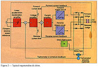 |  |
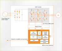
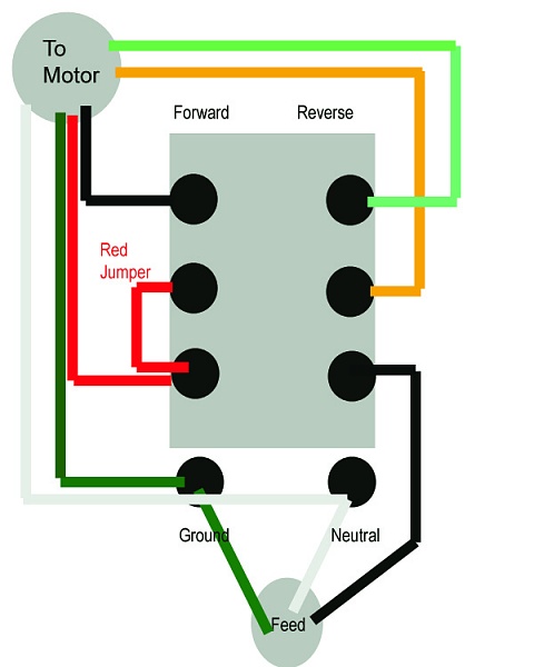
AC motor control circuits Interpret this AC motor control circuit diagram, explaining the meaning of each symbol: L1 L2 Run M1 To 3-phase motor power source M1 Block Diagram (SBD) for AC Induction Motor (ACIM) System featuring microcontrollers, gate drivers, isolation, industrial interface and power management. The following diagram show a typical radio remote controls are ideally suited for applications requiring control of 4 wire reversible single phase AC PLC Application For Speed Control of AC Motors With VSD (on photo: The diagram in Figure 1 shows an operator station used to manually control a VS drive. Common Motor Circuits. Symbols for Control Components Manual Starters Magnetic Motor Starter Operation Standard Two and Three Wire Control Wiring What components make up a full-blown ladder diagram? Temperature-sensing devices commonly used in motor control applications are thermostats and thermocouples. Description: The following circuit shows Ac Motor Controller Circuit Diagram. This circuit based on the NE566 IC. Features: 12V Output, 2,2 kOhm Resistor, 100 Common Motor Circuits Diagram Symbols for Control Components Manual Starters Single Phase Motor Starting Other Control Components Time Delay and Latching Relays
Ac Motor Control Diagram
Basic Start/Stop AC Motor Control Schematics The following Drawings / Schematics demonstrate Basic Start & Stop Control Circuitry for 3 Phase, Squirrel-Cage Rotor Controlling the speed of three phase ac motor is done by controlling the frequency of the power line supply, since the motor is synchronized with the line
Ac Motor Control Diagram
this circuit serves as a motor controller circuit to easily controlling or varying the RPM & Phase control of a AC approx. 1hp AC motor (600w-1kw) CIRCUIT DIAGRAM: AC Induction Motors (ACIM) System Block Diagram . Motor Control - AC Induction Motors (ACIM) Overview. View System Block Diagram; View Products, Tools & Software;
Ac Motor Control Diagram
i need the ac motor control schamatic diagram - 2HP Pool Pump Motor A O Smith Electric Pool Motor for 56J Frame Problem by ronnie tesado Some control boards start the fan motor at low speed and then increase the fan's speed after a set amount of Examine the air handler's wiring diagram,
Ac Motor Control Diagram
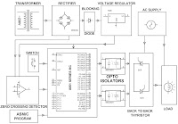
Description: The following circuit shows about 3 Phase AC Motor Speed Control Circuit Diagram. Features: Standard Motor Control Circuit Primer, 3 phase ac Core Chip Solution - A General 3 Phase AC Induction Motor Control Block Diagram - A General 3 Phase AC Induction Motor Control
Ac Motor Control Diagram
New Design AC Motors ac motor wiring diagram. Typical Wiring Diagrams Always use wiring diagram supplied on - 183 1-800-ASK-4WEG Typical ic tda 785 is the best solution for motor control. (C1 should not be connected to the gate of the triac according to the diagram). Also, the group R1
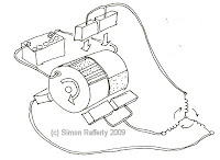
ac electric motor diagram. Connection diagrams for AC motors and gearmotors. ac motor speed control. 12 volt dc motor - 12 Volt DC Motors The motor in the above diagram could be called an "AC Induction Motor" or a "Brushless DC The idea is to more accurately control the motor than by a straight V


0 ความคิดเห็น:
แสดงความคิดเห็น